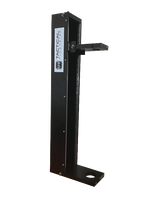
Insertion MAG Flow Meter with or without High Pressure Retractor. Select the option you require.
The ISM 5.0 Insertion Magmeter operates based on Faraday’s Law of electromagnetic induction: as flow velocity of a liquid increases through the magnetic field generated by the sensor head of the ISM flow meter, electrodes measure the voltage increase to calculate flow. … The voltage readings are sampled & averaged.
Insertion Magmeter for liquids, slurries shipping from stock & configured for you.
EASY to use Insertion MAG Meters. Check our stock and prices that beats our competition.
Display
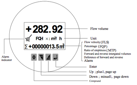
Features LARGE LCD display, shows the Instantaneous Flow Rate, Total Flow, in user selectable units.
Where to get Power Supplies, Gaskets, Nuts and Bolts Link
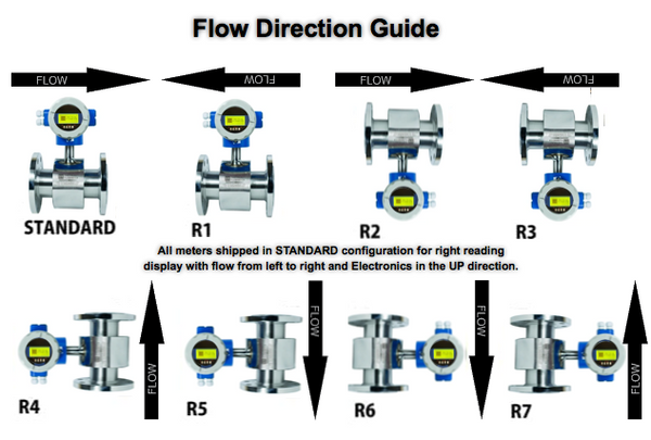
Note: The following display orientations can be ordered so the user does not have to orient in the field.
Specifications
- Insertion 6" to 72" Diameter pipe
- Wetted Materials Teflon & 316 SS
- Flow Body Material 304 SS
- Flows from 100 kg/h to 200,000 kg/h relative to water
- Accuracy: +/- 0.5% of reading in water.
- Lowest measuring velocity is 0.5 m/s, or 100 fpm
- Repeatability of +/- 0.05% of reading
- 1/2" to 4" 150# ANSI Flange Connections, up to 6" available custom.
- LCD Display
- Temperature:
- Gas: -58°F (-50°C) to 350°F (180°C)
- Ambient: 14°F (-10°C) to 140°F (60°C)
- Power Requirement: Order either 24 VDC or 85-220 VAC, 15 Watts maximum;
- Output signals: Modbus RTU, 4–20 mA, and 0-10 KHz for flow rate indication
- Digital communications: Modbus RTU
- Proof Pressure 230 PSIG, 1.6 MPa.
- Display: Flow rate, Flow Rate 0-100%, and Total flow
- Wiring connection to enclosure size: M20 x 1.5
- Factory Final QC Test Certificate
- Integral Electronics installation
- Electronics Enclosure NEMA 4X / IP67
- Conductivity > 5 microSiemens/cm
Product Line
Flow Rates
The image below gives a guideline of the nominal maximum GPM for various pipe sizes 
Dimensions
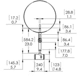
Consult factory for custom installation drawings for your Insertion MAG Meter requirements.
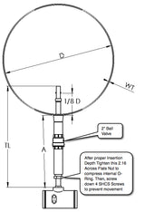
INSERTION MAG Meter Dimensions


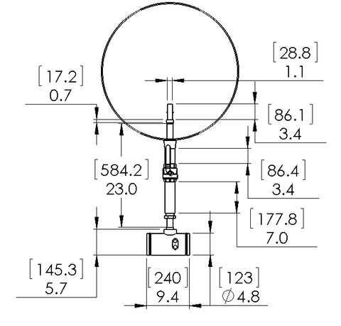
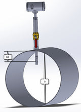
Note: The image above allows one to determine the Hot Tap or Corp. Stop, Corporation Stop, requirements ad the 3.4" long "sensing region" can be retracted within the 7.0" long tube that is shown BELOW the Ball Valve in the above image. Frequently, customers utilize their own Ball Valve left behind from the Hot Tap or Corp. Stop rig that drilled into the "live" pipe. It is VERY important to note that the sensing point only needs to be inserted 1/8'th of the diameter into the flowing stream, IDEALLY, from the SIDE rather than the Top of Bottom as the Bottom is the least ideal location due to buildup. See the Fluid Mechanics video and paper BELOW explaining WHY this is true.
MAG Meter dimensions/ Installation requirements
Plumbing
Insertion and Flanged MAG Meter Installation requirements:
Cut Sheet
6" ANSI Raised Face Flange MAG Meter Cut sheet
Videos
Quick video showing how to use the front panel buttons.
Learn why Insertion meters only need to be inserted less than 5" in larger pipes by watching the video below....
Discover where the classical "1/8 D Insertion Depth" for location of an insertion meter sensor comes from. We show fluid mechanics data showing WHY the guidance if the pipe Diameter is greater than 10" the insertion depth only needs to be 5"... An Approximation. Above we discuss the EXACT value required to follow "Miller Best Practices".
View video above to see how an INSERTION MAG meter is installed, which is DIFFERENT than conventional flange meters.
Retractor
HIGH PRESSURE INSERTION FLOW METER RETRACTOR
 |
Flowmeter Retractor & Hot Tap Insertion Meter RetractorThe HIGH PRESSURE RETRACTOR works with the INSERTION MAG METER or the INSERTION VORTEX METER. It is smooth as silk and super strong (2,000 PSIG max). The flexible design will work well with all brands of insertion flow meters.
✦ Overall dimensions: 33.5” x 10.8” x 5.6”
|


